
News

Date2020-10-31/ Research Highlight
Recently, the research group of Prof. Xiao Wei Sun and Assoc. Prof. Kai Wang ( Electronic and Electrical Engineering) at Southern University of Science and Technology (SUSTech) and Prof. Weidong Zhuang of General Research Institute for Nonferrous Metals has made new progress in the field of blue InP quantum dot display. Their work was published in the internationally renowned academic journal Advanced Functional Materials, entitled “InP/ZnS/ZnS Core/Shell Blue Quantum Dots for Efficient Light-Emitting Diodes.”
QLED is a device that uses quantum dots (QDs) as luminescent materials, which have the characteristics of wide color gamut, high light efficiency, low power consumption, inkjet printing, and flexibility. As a representative of Ⅲ-Ⅴ semiconductor materials, InP QDs have a large exciton Bohr radius, strong quantum confinement effect, and no mercury, cadmium, lead, and other heavy metals. At the same time, it has excellent stability and has a broad application prospect.
QDs independently emit three primary colors of red, green, and blue to form a pixel by adjusting the three colors’ proportion to generate color pixels. Red, green, and blue light sources are all significant for display, and none of them are indispensable. At present, there is a big gap between the performance of blue light QLED and red light and green light, which has become one of the main bottlenecks restricting the development of full-color InP QLED.
At present, the mainstream InP synthesis route uses tris(trimethylsilyl)phosphine [(TMS)3P] as the source of P. (TMS)3P is expensive and will generate highly toxic phosphine gas when in contact with air. In this work, we used cheap (1/80 times) and stable tris(dimethylamino)phosphine [(DMA)3P] as the P source, InX3 (X=Cl, Br, I) as the In source, Oleylamine was used as a solvent. By changing the ratio of different halogen elements, InP cores with different particle sizes can be obtained. By choosing ZnS (3.68 eV) as the shell layer, the excitons are completely confined to the core, and the redshift of the spectrum caused by the core electronic transition is avoided. A pure blue InP/ZnS QDs with an emission peak of 468 nm can be obtained.
It is found that the excess zinc stearate added in the shell coating process prefers to coat on the QDs as clusters or grow into zinc stearate microspheres after the reaction. However, it is difficult to remove the zinc stearate completely. Zinc stearate on QDs can be purified by chloroform as the solvent, and the QY of the QDs is sacrificed and reduced to 18%. The reason for the decrease of QY is mainly due to the strong polarity of chloroform as solvents. In the process of purification, the ligands on the surface of QDs will undergo desorption in a solvent of high polarity, which leads to a decrease of QY. To completely remove zinc stearate, increase the shell thickness of QDs, and avoid too much decrease of the QY of QDs, we used S-TOP to react with zinc stearate. Excess S-TOP reacted with the residual zinc stearate. At the same time, the generated ZnS monomer could be coated on the surface of the InP/ZnS QDs, which increased the thickness of the shell. When the thickness of the shell increases, the stability of the QDs also improves obviously. The QY of the InP/ZnS/ZnS QDs shows a 50% decrease under the illumination of a 365 nm Hg lamp with a power density of 8 mW cm2 and irradiation done for 10 hours, compared to a 77% decrease of the InP/ZnS QDs.
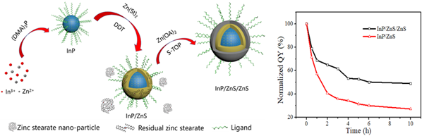
Figure 1. Schematic illustration for the synthesis of thick shell InP/ZnS/ZnS QDs and the test of PL QY of InP/ZnS and InP/ZnS/ZnS QDs.
The maximum current efficiency of the InP/ZnS/ZnS QLED is 3.6 cd A1, which is nearly three times as high as that of InP/ZnS QLED (1.3 cd A1). The maximum EQE also increased by three times, i.e., from 0.6 to 1.7% measured from 14 devices, which is the highest value reported in the literature at present. The brightness of InP/ZnS QLED increases from 25 cd m2 to 140 cd m2 at 6V. The current density also improved from 32 mA cm2 to 125 mA cm2 at 8 V. At the same time, due to the improved carrier injection efficiency, the turnon voltage drops from the original 4.2 eV to 3.1 eV.
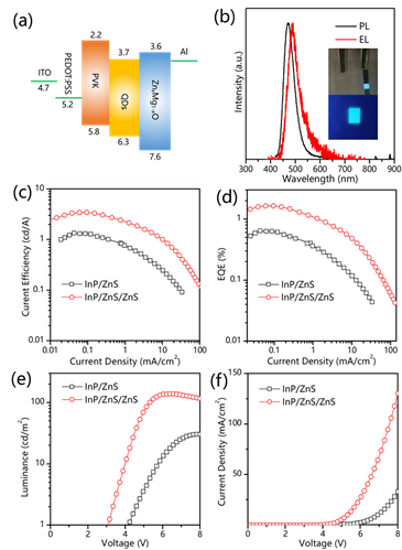
Figure 2. a) Energy level diagram for QLED devices. b) PL and EL spectral of InP/ZnS/ZnS QDs. Device characteristic of InP/ZnS and InP/ZnS/ZnS QLED: c) Current efficiency versus current density. d) EQE versus current density. e) Current density versus voltage. f) Luminance versus voltage.
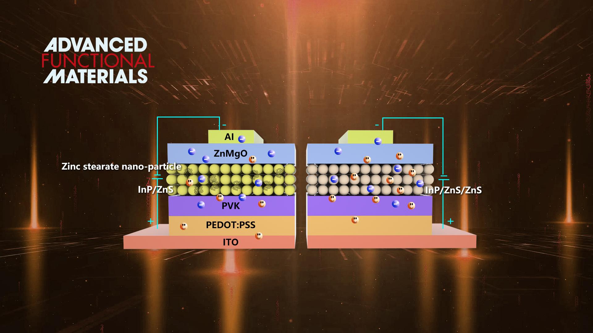
The improvement of device performance is mainly due to two factors. Firstly, the increase of the shell thickness of QDs can reduce the energy transfer in the QLED. Secondly, the residual zinc stearate is reacted with S-TOP, which reduces the barrier of hole injection. This research has greatly promoted the progress of blue InP QLED in the field of light-emitting display.
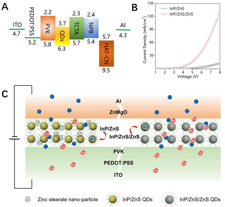
Figure 3. Schematic illustration for the comparison of InP/ZnS QLED and InP/ZnS/ZnS QLED carrier injection efficiency
Wenda Zhang and Shihao Ding are the co-first authors of the paper. Professor Xiao Wei Sun, Associate Professor Kai Wang of SUSTech, and Professor Weidong Zhuang of GRINM are co-corresponding authors.
This work was supported by the National Natural Science Foundation of China, National Key Research and Development Program of China, Natural Science Foundation of Guangdong Province, Guangdong University Key Laboratory for Advanced Quantum Dot Displays and Lighting, Guangdong Province’s Key R&D Program, Shenzhen Key Laboratory for Advanced Quantum Dot Displays and Lighting, Shenzhen Innovation Project.
Link to the article :
https://onlinelibrary.wiley.com/doi/10.1002/adfm.202005303